Grounding performance is not necessarily unchanged between routine inspections. Soil conditions, corrosion, aging connections and equipment problems can cause grounding conditions to vary over time.
An electric power grid grounding monitoring system addresses this gap by continuously collecting grounding and device information and presenting the data through a centralized monitoring platform.
Why Grounding Monitoring Needs Continuous Data
Periodic grounding tests provide useful information about the condition of a grounding point at the time of inspection. However, they do not show what happens between two scheduled tests. Continuous monitoring adds this missing period of information and makes changes easier to track.
Monitoring Changes Between Inspections
A grounding point may show acceptable resistance during one inspection and experience a change several weeks later. Without continuous measurements, that change may not be identified until the next scheduled test.
An electric power grid grounding monitoring system records measurements throughout the interval, allowing operators to see when an abnormal change occurs and how the condition develops.
Tracking Grounding Resistance Over Time
Individual resistance readings provide a snapshot of grounding performance. A continuous record, on the other hand, shows the development of resistance over time.
With an electric power grid grounding monitoring system, current readings can be viewed together with historical measurements. Maximum, minimum and average values can also be used to examine resistance behavior over a selected period.
Monitoring Distributed Grounding Points
Grounding points within substations, transmission facilities and other power assets may be distributed across different locations.
An electric power grid grounding monitoring system collects information from these points into a unified monitoring environment. When an abnormal condition occurs, operators can identify the corresponding location without having to check every grounding point in the field first.
Key Information Collected by the Monitoring System
Grounding resistance is a central measurement, but effective remote monitoring also requires information about location, communication and device condition.
Grounding Resistance and Historical Data
Real-time resistance indicates the latest condition of a monitored grounding point, while historical data shows how that condition changes.
An electric power grid grounding monitoring system can retain resistance records and provide maximum, minimum and average values for selected periods. This makes it possible to compare current measurements with previous behavior rather than evaluating each reading independently.
GIS Location and Grounding Status
Grounding data becomes easier to manage when it is connected with the physical location of each monitoring point.
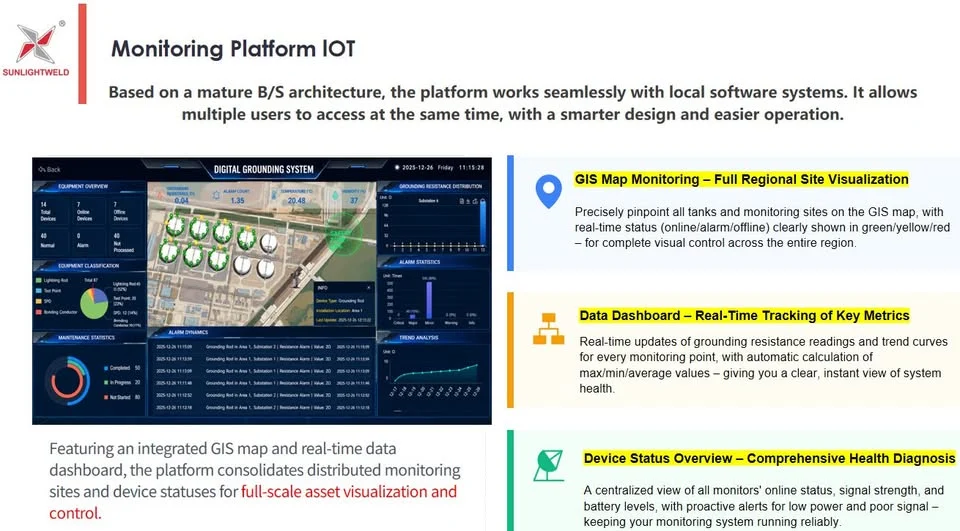
Through GIS visualization, an electric power grid grounding monitoring system can display grounding points on an interactive map. Different states, such as online, alarm and offline, can be shown directly on the interface.
This allows an abnormal point to be associated with its corresponding field location.
Communication, Signal and Battery Information
A missing measurement does not always mean that the grounding system itself has developed a problem. Communication failure, weak signal strength or insufficient battery power can also interrupt monitoring data.
For this reason, an electric power grid grounding monitoring system can monitor communication status, signal strength and battery condition together with grounding resistance. This helps distinguish a grounding issue from a monitoring-device issue.
Grounding and Device Alarms
Continuous monitoring can provide automatic notifications when configured abnormal conditions occur.
An electric power grid grounding monitoring system can generate alarms related to grounding resistance, battery levels and communication problems. Operators can then focus on locations that require attention instead of manually checking every recorded measurement.
Sunlight Grounding Electric Power Grid Grounding Monitoring System
Sunlight Grounding integrates field monitoring equipment, GIS visualization, data analysis and intelligent device management into a Web-based IoT platform.
The electric power grid grounding monitoring system is designed for distributed grounding networks that require centralized access to grounding conditions and monitoring-device information.
Centralized GIS Monitoring
The Sunlight Grounding platform uses a GIS interface to display monitored grounding points and their locations.
Grounding points can be identified according to online, alarm or offline status, providing operators with a visual overview of the network and helping them locate points that may require attention.
Grounding and Device Data on One Platform
The platform combines grounding resistance measurements with historical records and monitoring-device information.
Using the electric power grid grounding monitoring system, operators can view resistance, communication status, signal strength and battery information within the same monitoring environment rather than reviewing separate data sources.
Web-Based IoT Platform
The Sunlight Grounding system is built on a Web-based IoT architecture for centralized monitoring and multi-user access.
The electric power grid grounding monitoring system can connect monitoring points across distributed locations, while system integration can be supported according to project interfaces and deployment requirements.
Connecting Distributed Monitoring Points
The monitoring platform links field grounding points with centralized visualization, historical information and alarm functions.
This structure can be used for deployments covering individual facilities as well as larger networks with grounding assets distributed across multiple locations.
Conclusion
An electric power grid grounding monitoring system extends grounding management beyond periodic measurements by continuously recording resistance and related device information.
Historical resistance trends, GIS location, device status and alarm data provide a clearer view of changes occurring across distributed grounding points.
For power infrastructure with grounding assets located across multiple sites, continuous monitoring provides a practical way to identify abnormal conditions and support targeted field inspection.
www.sltup.com
Sunlight Grounding

 0
0
 0
0 


